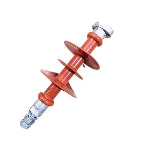
Composite Suspension Insulators
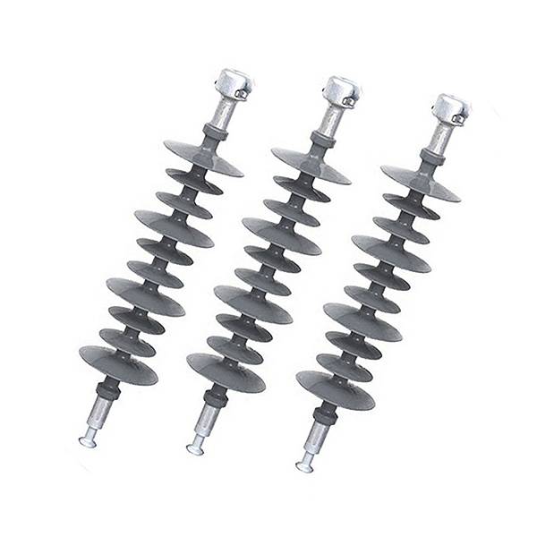
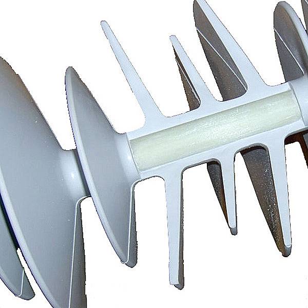
Composite suspension insulators:the silicon rubber rain shed, designed according to the aerodynamics principle, use the whole-moulding method, to make sure the validity of total creepage distance under every climate and nasty conditions, as well as improved the pollution discharge of the insulators;The fiber rod uses the ECR high-temperature and acid-proof material; The end fitting connection adopts the zinc cover protection, supersonic monitor and coaxial constant compression controlled by computer, finished with good appearance and high quality.
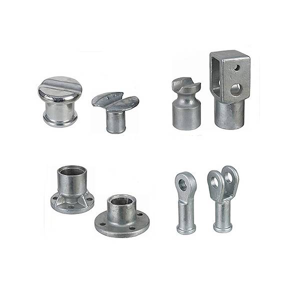
Different metal end fitting show ,suspension insulator,long rod insulator,Polymer insulator,cap and pin insulator,Isolator Insulators.
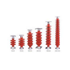
Different color show ,insulator manufacturers,hollow insulators,power line insulators,power line insulator,polymer post and suspension insulator.
The Feature Of Our Compsoite Insulators
1) Silicon Rubber for sheds/ housing
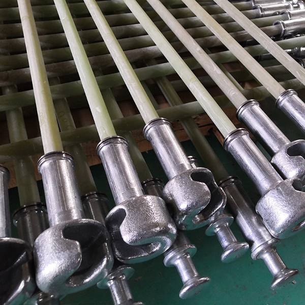
2) Glass-fiber reinforced epoxy resin rod (ECR type) for core
3) Hop dip galvanized cast steel for metal fittings
4) Rated voltage:10KV~220KV
5) 5000hours aging test.
6) IEC Standard.
Fiberglass Rod Specificationthe Datasheet Of Composite Suspension Insulators
|
Insulator Mode |
Rated Voltage (KV) |
Rated mechanical tensile load (KN) |
Connection structure mark |
Structure Height mm |
Minimum distance ArcL. |
Minimum nominal Creepage distance mm |
Full-wave Lightning Impulse withstand voltage (peak) |
Min.wet withstand voltage per minute at power frequency |
|
FXWB4-10/100 |
10 |
100 |
16 |
400±15 |
200 |
365 |
110 |
50 |
|
FXWB4-35/70 |
35 |
70 |
16 |
630±15 |
450 |
1015 |
230 |
95 |
|
FXWB4-35/100 |
35 |
100 |
16 |
650±15 |
450 |
1015 |
230 |
95 |
|
FXWB4-66/70 |
66 |
70 |
16 |
935±15 |
700 |
1900 |
410 |
185 |
|
FXWB4-66/100 |
66 |
100 |
16 |
935±15 |
700 |
1900 |
410 |
185 |
|
FXWB4-110/70 |
110 |
70 |
16 |
1240±15 |
1000 |
3150 |
550 |
230 |
|
FXWB4-110/100 |
110 |
100 |
16 |
1240±15 |
1000 |
3150 |
550 |
230 |
|
FXWB4-220/100 |
220 |
100 |
16 |
2150±15 |
1000 |
6300 |
1000 |
395 |